Custom Common Mode Line Filters for Effective Noise Suppression
A Common Mode Line Filter is a passive electromagnetic component designed to allow the desired electrical signals to pass through power or data lines, while effectively suppressing unwanted high-frequency noise originating from external sources or internal circuit interference.
At Shenzhen Kunyo, we specialize in meeting customer requirements through customized designs. Our expertise lies in producing chokes and inductors precisely engineered to match your application, ensuring the exact impedance and performance you need.
We offer a comprehensive range of custom inductor and filter services, guiding you seamlessly through the entire design and manufacturing process—from initial concept to final product.
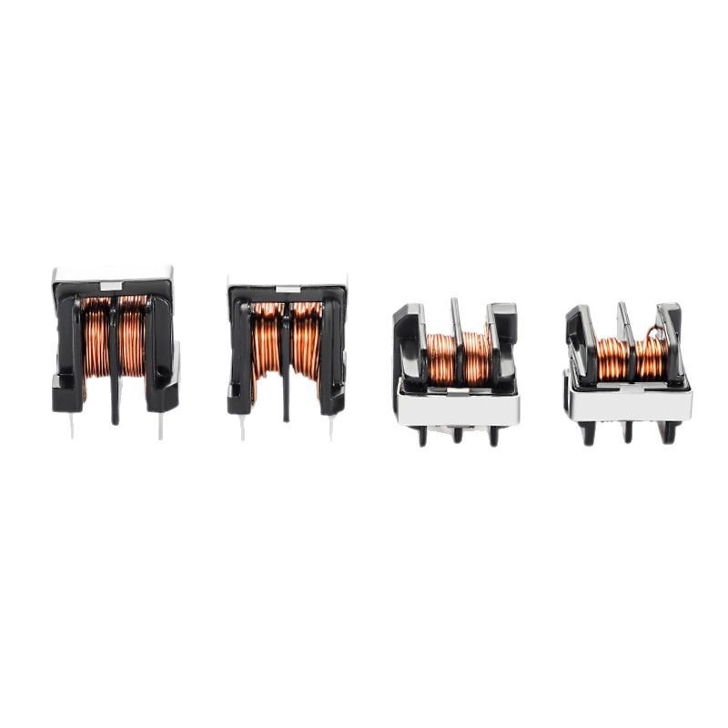
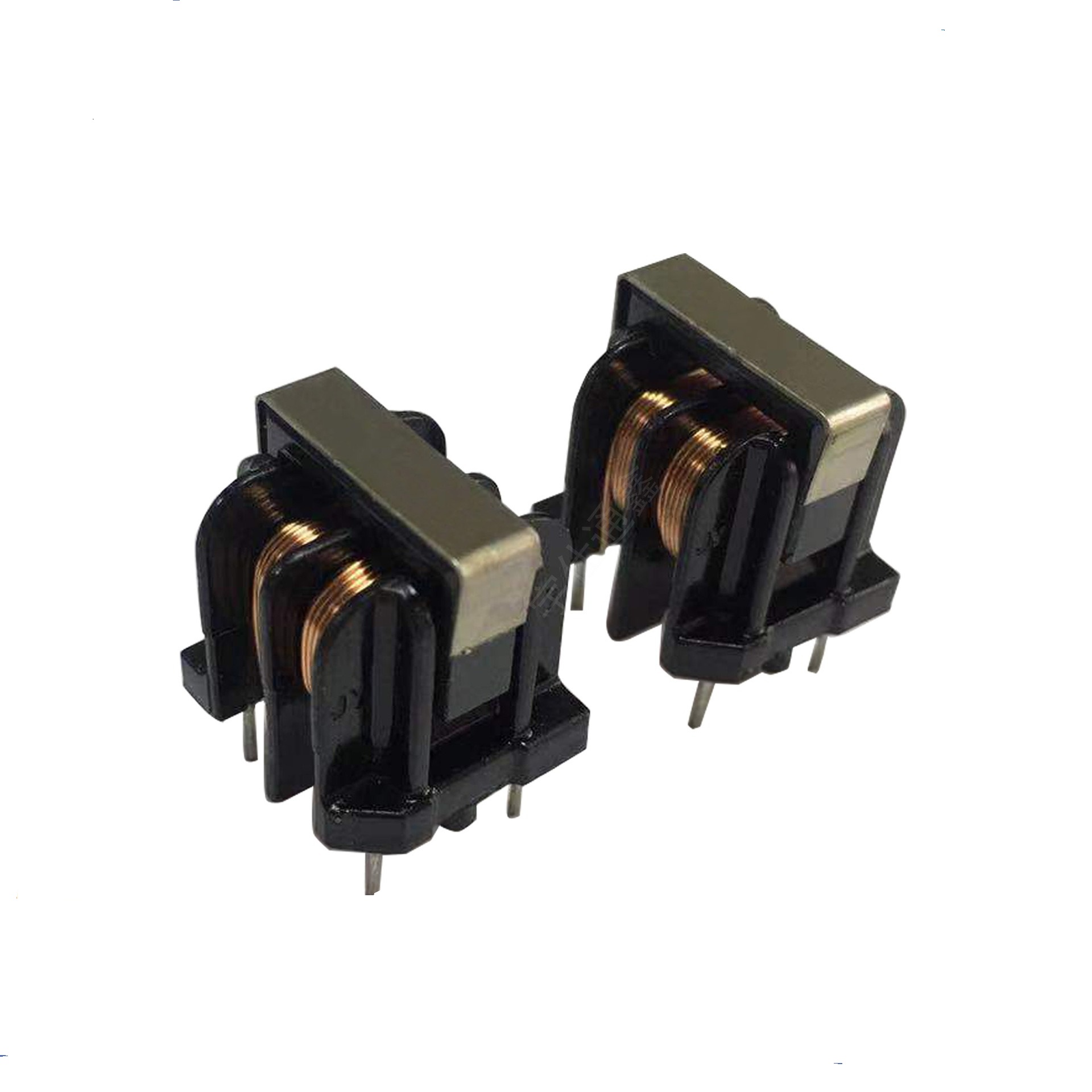
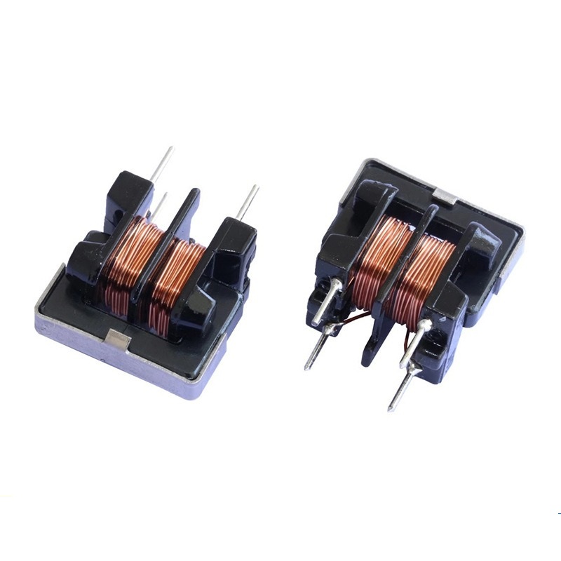
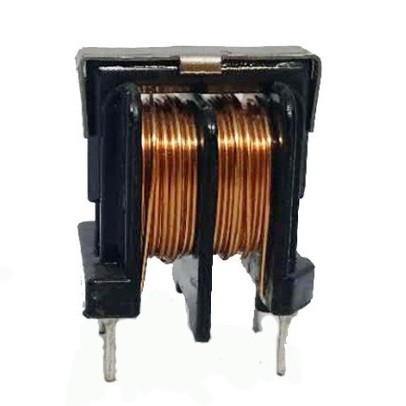
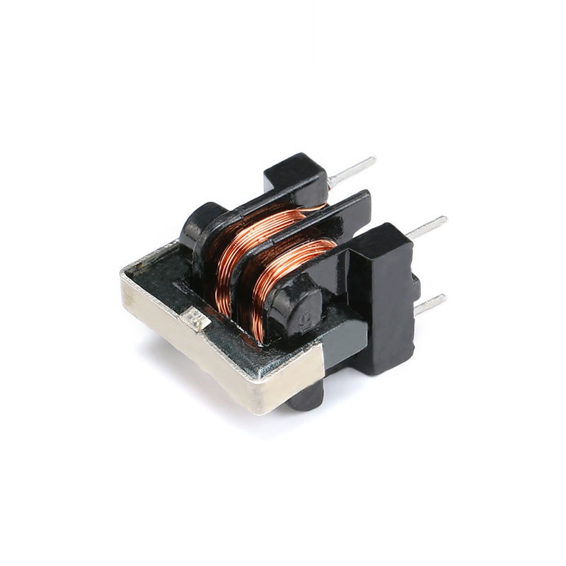
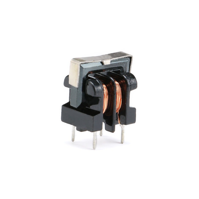
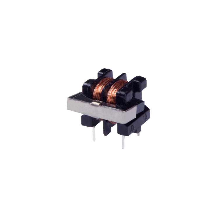
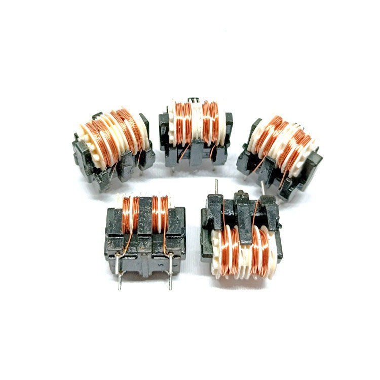
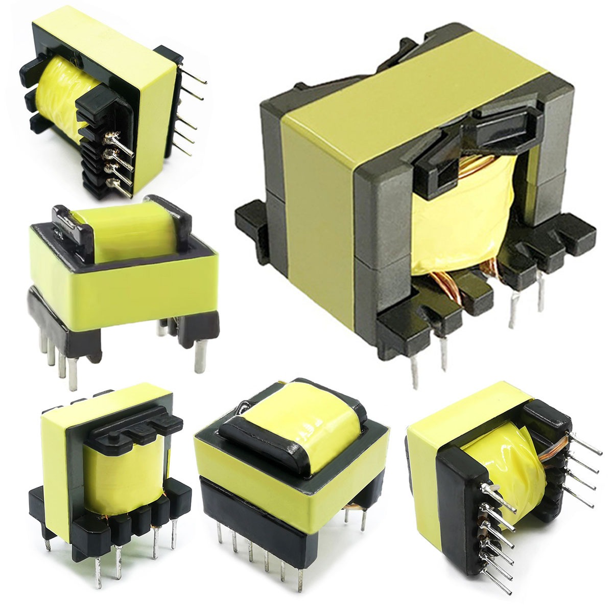
Common mode line filter is a common type of coil inductor structure, typically featuring a dual-wire wound configuration. It consists of two parallel coils, connected through a magnetic material (such as a ferrite core), which enhances the electromagnetic coupling between the coils and results in a high inductance coefficient. It utilizes magnetic materials as leads and it usually has a U-shaped profile, and includes pinholes. A common mode line filter is an electronic component used for signal filtering in electronic circuits and electromagnetic interference (EMI) suppression in power circuits . Common mode filters are widely used in filtering, resonant circuits and other applications, effectively suppressing differential-mode noisewhile mitigating interference sources.
How to design the Common Mode Line Filter
The design of a common mode line filter requires careful consideration of parameter selection and optimization.
1. Inductance
When designing a common mode line filter, it is essential to accurately determine the required inductance value. This value is typically based on the specific circuit requirements, operating frequency, and desired filtering performance. Proper inductance selection ensures that the filter effectively suppresses unwanted noise and high-frequency interference while maintaining signal integrity for the intended application. Choosing the correct inductance also helps minimize voltage drops and power loss, improving overall system efficiency and reliability. High-quality inductors with precise inductance values are critical in applications such as power supplies, communication devices, industrial automation, and consumer electronics.
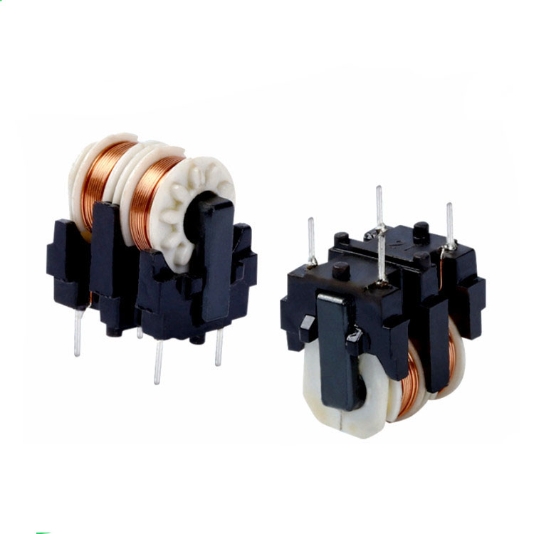
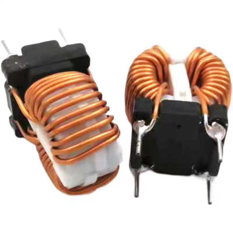
Selecting the appropriate core material and winding method is a crucial step in designing an efficient common mode line filter. The winding technique,such as layered, bifilar, or interleaved winding should be chosen based on the desired coil size, current capacity, and space constraints of the PCB layout. Meanwhile, core material selection must consider magnetic permeability, saturation characteristics, and cost efficiency. Using materials with high permeability and low core loss, such as ferrite or powdered iron, allows for better electromagnetic suppression and improved thermal performance. Properly matched materials and winding methods ensure the filter delivers high performance, compact design, and long-term stability.
In designing a common mode line filter, careful attention must be given to electromagnetic interference (EMI) interactions with surrounding components. Poor EMI management can lead to signal distortion, noise coupling, and reduced system reliability. Designers must consider PCB layout, component placement, and shielding techniques to minimize interference. Effective EMI management not only ensures that the filter performs optimally but also helps devices meet international EMC standards. By controlling EMI interactions, engineers can improve signal clarity, system efficiency, and long-term reliability across applications ranging from switch-mode power supplies and industrial controllers to consumer electronics.
The design parameters of a common-mode line filter affect its electrical performance. Below are some common technical parameters:
Rated Inductance
he rated inductance of a common-mode line filter refers to its inductance value at a specific operating frequency. Inductance is typically measured in microhenries (µH)—the higher the value, the greater the impedance to low-frequency signals.
DC resistance represents the resistance to direct current flowing through the inductor. A lower DCR reduces power loss and heat generation in the component.
This is the maximum allowable current that can pass through the inductor under normal operating conditions. Exceeding this value may cause coil overheating or even component failure.
This is the highest permissible temperature at which the component can function reliably. Exceeding this limit may lead to deformation or performance degradation.
This defines the minimum and maximum frequencies at which the filter maintains its rated performance. If the operating frequency exceeds this range, the component may fail to function properly.
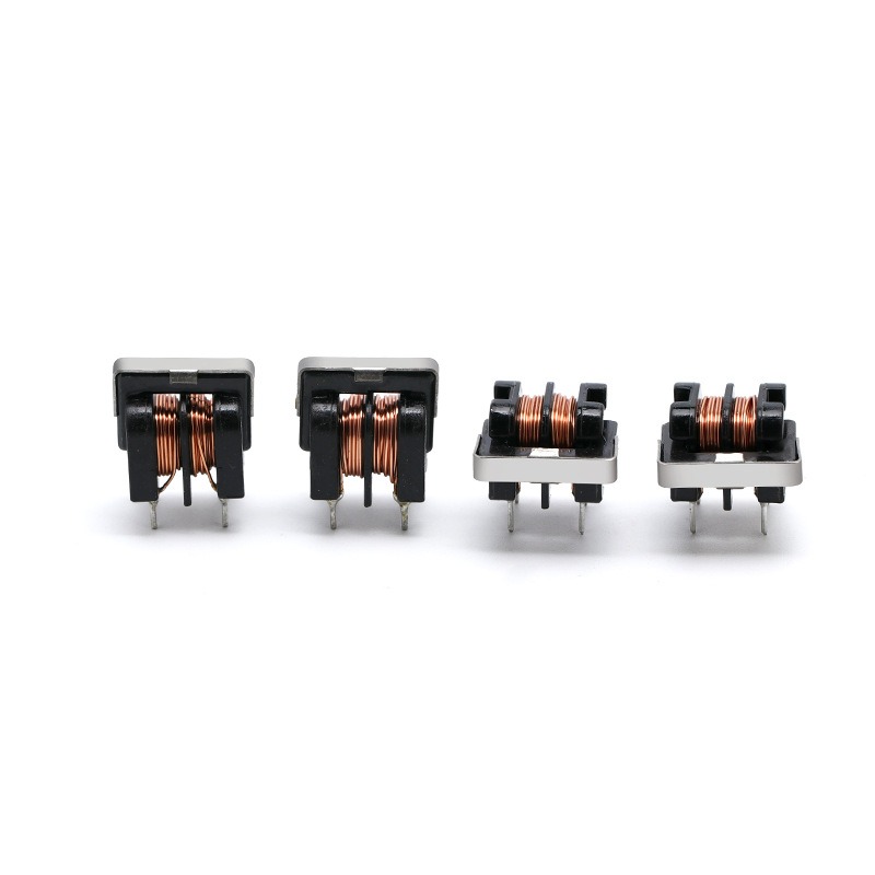
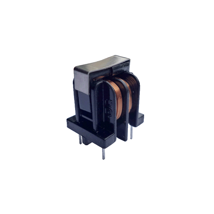
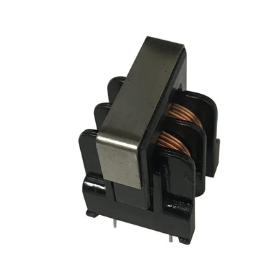
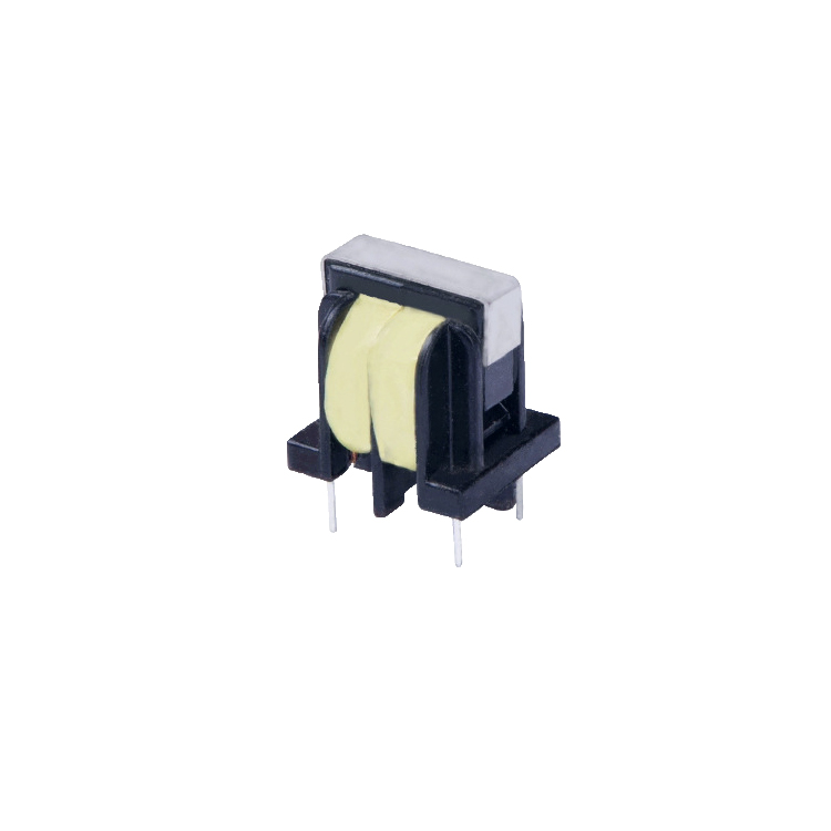
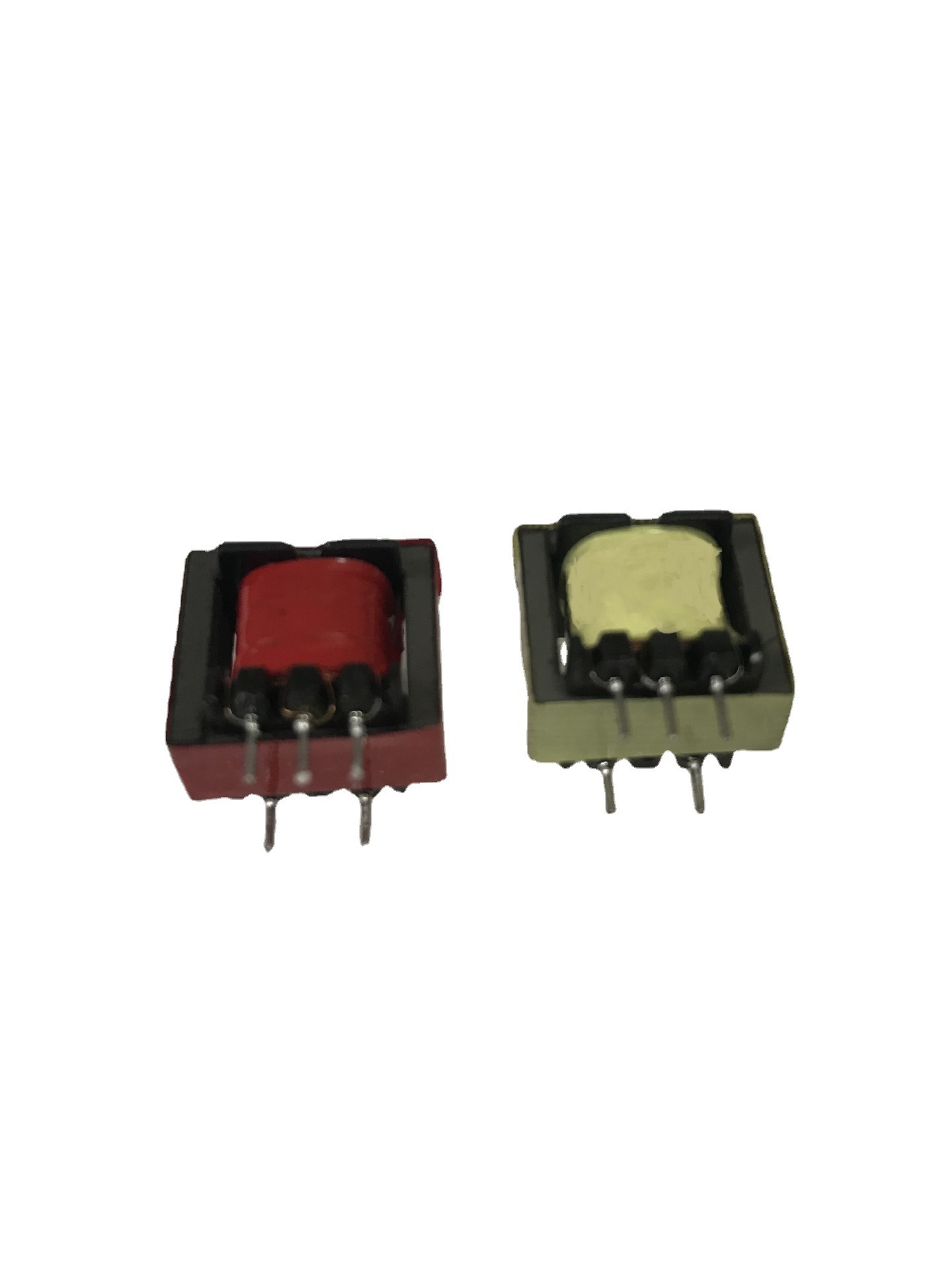
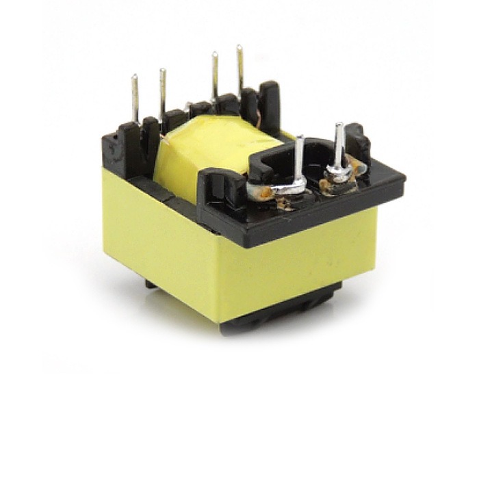
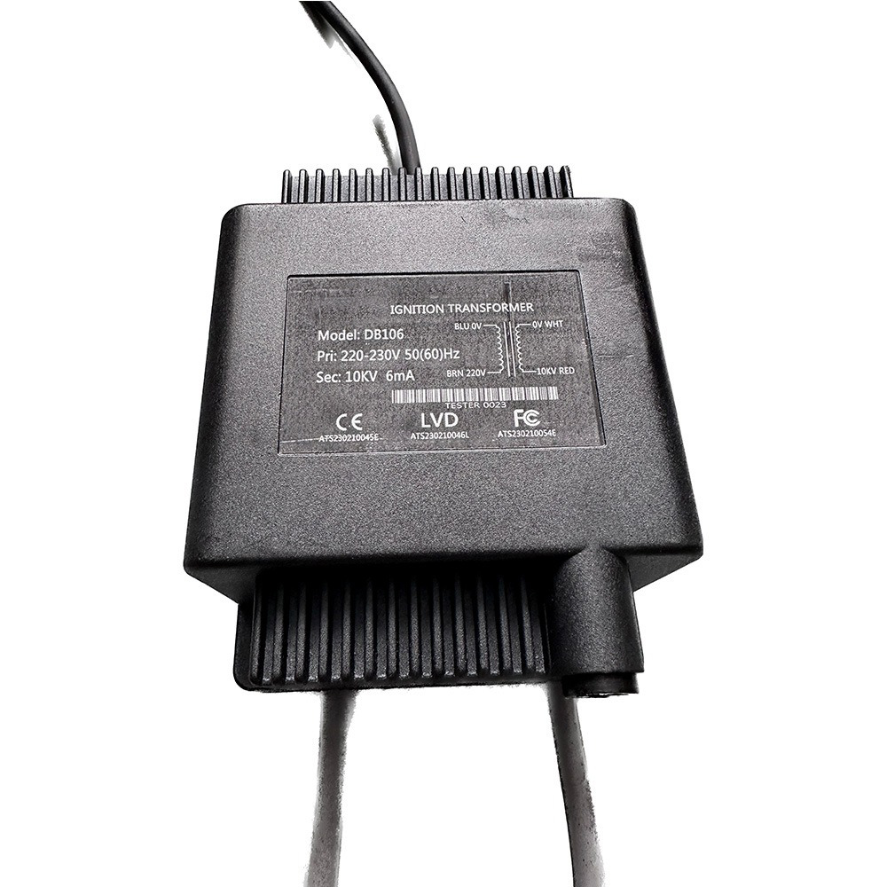
Common-mode line filters are available in various packaging styles, such as open-frame, surface-mount (SMD), and flat-wire coil design. Selecting the appropriate package helps optimize circuit layout and installation.